


How building automation impacts health, efficiency, and indoor air quality in hospitals
How does building automation ensure hospitals are safe, secure, comfortable environments for everyone?


The technological advances in the HVAC industry over past two decades have helped building systems operate in a more energy-efficient manner. There is no shortage in the building industry of buzz phrases such as smart buildings or green buildings.
However, regardless of how energy-efficient a building is, if it is not a net-zero building, the systems within it still use energy—in many cases, significant amounts of energy. According to the U.S. Energy Information Administration, “When electrical system energy losses are included, the residential and commercial sectors accounted for 21 percent and 18 percent, respectively—40 percent combined—of total U.S. energy consumption in 2022.”
Although design engineers and building owners strive to design and install energy-efficient HVAC equipment and lighting fixtures, having this efficient equipment in a building is not an indication the building will be energy efficient; it is a first step toward having an energy-efficient building. The building automation system plays a crucial role in the overall energy consumption levels of a building.
Until the late 1980s, HVAC controls systems in commercial buildings were mostly pneumatic based: on/off control systems in which pumps and fans were left “riding their curves” based on the load. Variable frequency drives and the concept of varying the speed of a pump or fan motor based on load was a relatively novel concept.
Similarly, the idea of having a building engineer receive alarms and notifications from a building automation system was in its infancy. Looking back, you could assume building systems could have performed better and used less energy.
The advent of direct digital control systems in the mid-1980s and the publication of the BACnet standard for building automation and control system networks provided the building industry with the potential and tools for reducing the amount of energy used by building systems.
BACnet is a communication protocol developed by ASHRAE. The standard is continuously maintained by the ASHRAE SSPC-135 committee.
It is common for direct digital control systems to talk with the cloud and with myriad apps, each marketed with promises to support the sustainability of the building, provide better control over the environment in the building, and, for building engineers and commissioning professionals, provide information (i.e., alarms, trends, diagnostics, energy performance, etc.) about the operation of the building systems.
Are smart buildings automatically energy-efficient buildings? What makes a building smart? A simple web search reveals as many definitions as there are links in the results page.
For example, a provider of internet-of-things devices may define a smart building as “a building that uses IoT devices to monitor various building characteristics, analyze the data and generate insights around usage patterns and trends that can be used to optimize the building’s environment and operations.”
A provider of information technology networks may define a smart building as one that “converges various building-wide systems—such as HVAC, lighting, alarms and security—into a single IT-managed network infrastructure.”
You could infer that what makes a building smart is in the mind of the beholder. The same could be inferred when describing a building as energy-efficient. To establish that a building is energy-efficient, we need a baseline.
Designing a smart building might start with a set of general requirements set by the building’s owner, while recognizing an energy-efficient or net-zero building doesn’t necessarily mean the building needs to be smart. Similarly, designing a smart building doesn’t mean the building is energy-efficient.
A couple of examples of broad performance requirements set by a building’s owner about what constitutes a smart building could be as follows:
The intent behind the BACnet standard as a performance requirement is to provide the controls contractor with a clear, concise set of requirements that must be met by any manufacturer of controls devices. It doesn’t matter to an owner who makes the controls device for a lighting controls system or HVAC control system, as long as controls devices carry a BTL Listing, said devices will speak the same language.
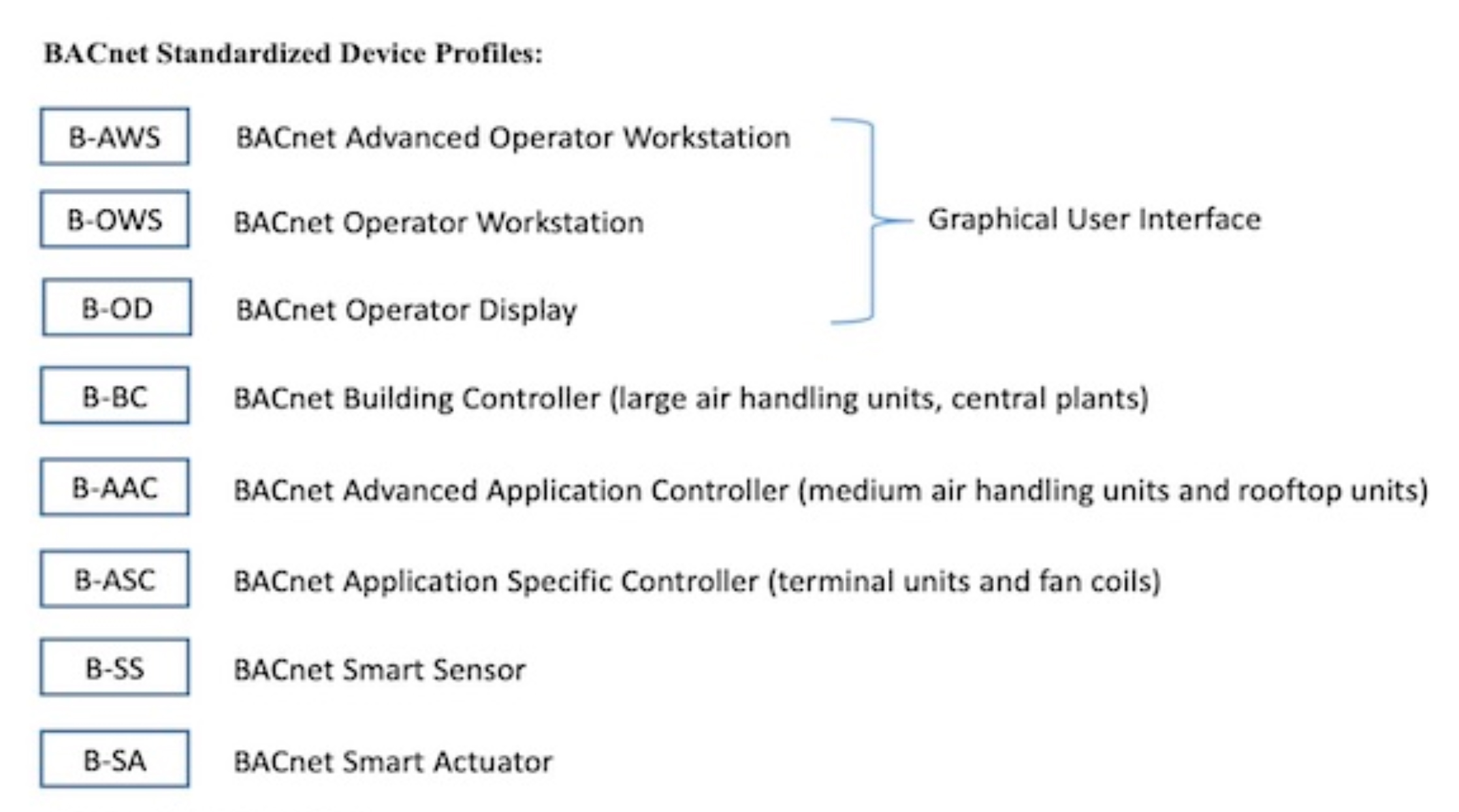
Figure1: BACnet device profiles.
The B-AWS and its tools allow future system changes under proper password protection, including dynamic creation, deletion, and modification of all configuration parameters, programs, graphics, trend logs, alarms, schedules, and every BACnet object used in the system.
For each device profile, the ANSI/ASHRAE 135 standard defines a minimum set of requirements the device must meet to be Listed as a BACnet device. It is important to note the difference between BTL Listed control devices and BACnet-compatible control devices. The fact that manufacturers may claim their product is BACnet compatible doesn’t mean it is also a BTL Listed device. At best, the claim may mean the control device can communicate with other BACnet devices.
For a control device to be BTL Listed, it must carry the BACnet Testing Laboratories stamp, which is an indication the device has been tested by a BACnet-certified laboratory and certified under the BTL Certification Program. The BTL website maintains a list of all BTL Listed control devices.
Each BTL Listed device is required have a protocol implementation conformance statement (PICS), a document that describes the options specified by BACnet that are implemented in the device.
A sample network architecture of a building automation system based on the BACnet communication protocol is shown in Figure 2.
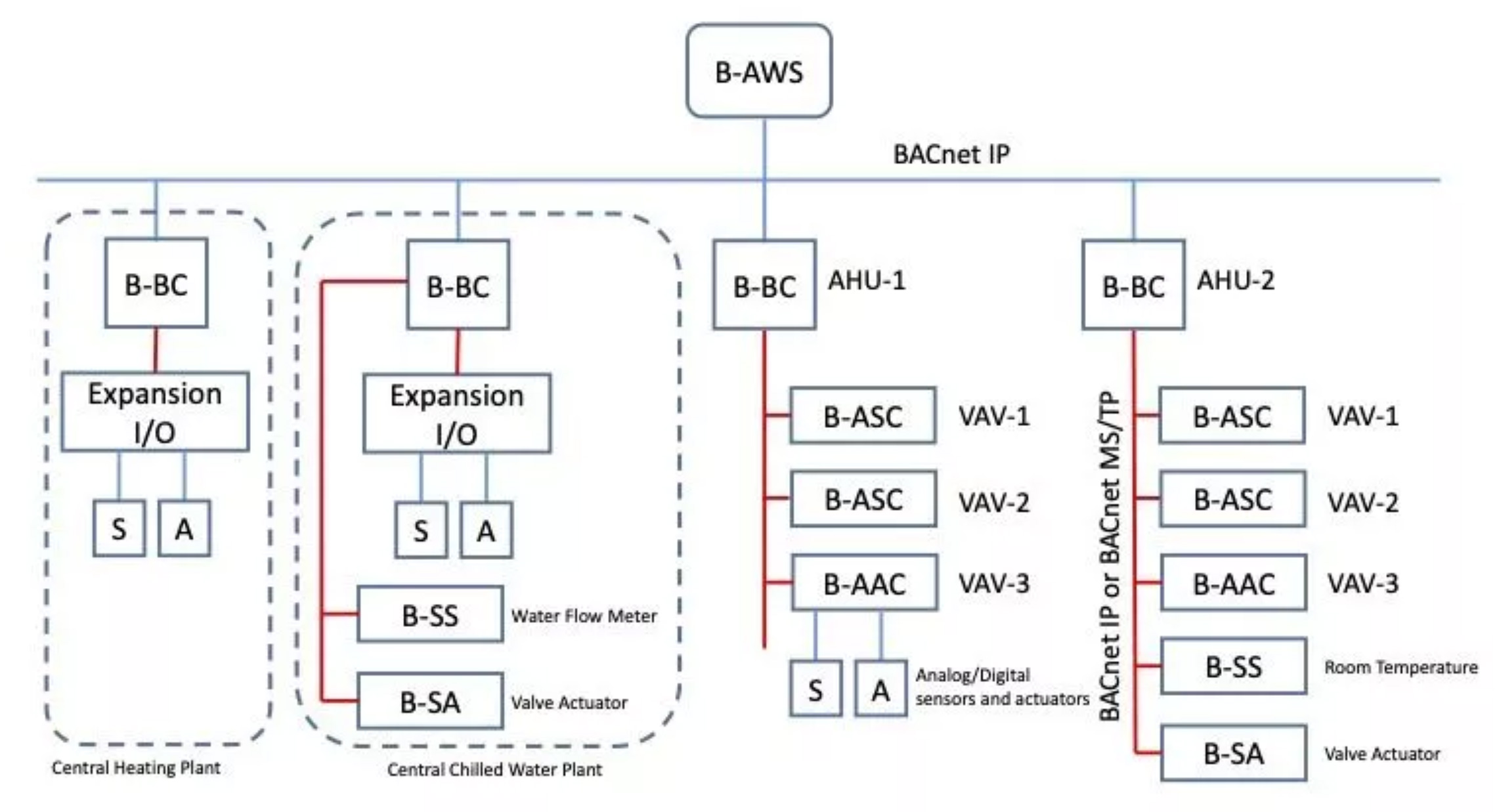
Figure 2: Sample BACnet network diagram.
The BACnet multi-drop serial-bus token passing (MS/TP) protocol is a peer-to-peer multiple-manager protocol that shares data by passing a token, or permission to “speak”’ across the network, between control devices (managers) that authorizes the holder device to initiate communication on the MS/TP network. Manager devices send requests, and subordinate devices submit responses.
Manager devices can request services from subordinate devices only if they have an available token. If the manager device doesn’t have a token, it must wait for a token to be passed to it. This is one of the main reasons for an MS/TP network to become slow, in particular when there is a high number of devices (more than 50) on the same bus. The control devices on an MS/TP network are connected in series via shielded twisted-pair cable, and the communication speed across the network is typically limited to 0.1 MB per second.
Unlike the devices on an MS/TP network, the devices on a BACnet internet protocol network are connected via Ethernet cable, and the network speed is typically greater than 100 MB per second.
A standard analog sensor (e.g., air temperature, chilled water temperature, etc.) can send an analog signal (typically resistance or volts) only to a BACnet control device. The control device then uses the analog signal for control of the HVAC equipment or shares (via BACnet communication protocol) the associated values from the sensor with other BACnet devices. The same principle applies to standard actuators. They are typically controlled by a BACnet control device via a 0- to 10-volt signal or 4- to 20-milliampere signal.
Figure 3 shows a sample PICS for a BACnet Smart Sensor (B-SS). The main difference between a BACnet Smart Actuator (B-SA) and B-SS and a standard analog or digital sensor or actuator is the BACnet devices are provided with a control board that allows them to be connected to a BACnet network and communicate with other BACnet devices on the network.
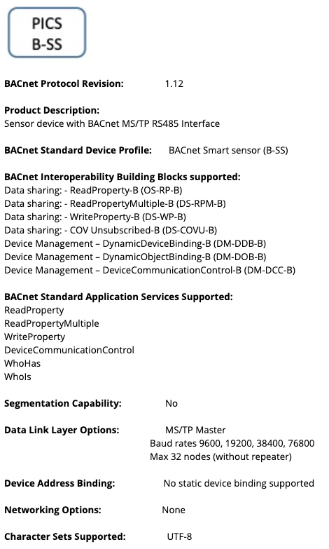
Figure 3: Sample PICS for a B-SS.
BTL Listed smart sensors and actuators are significantly more expensive than standard sensors and actuators, typically by an order of three or more.
Figure 4 shows two controls diagrams for the same variable air volume (VAV) box. In the diagram on the left of the figure, the control and monitoring of the VAV box and associated zone is done via standard analog and digital sensors and actuators. In the diagram on the right side, the control and monitoring of the VAV box and associated zone is done using a combination of standard analog and digital sensors and actuators and a B-SS and B-SA.
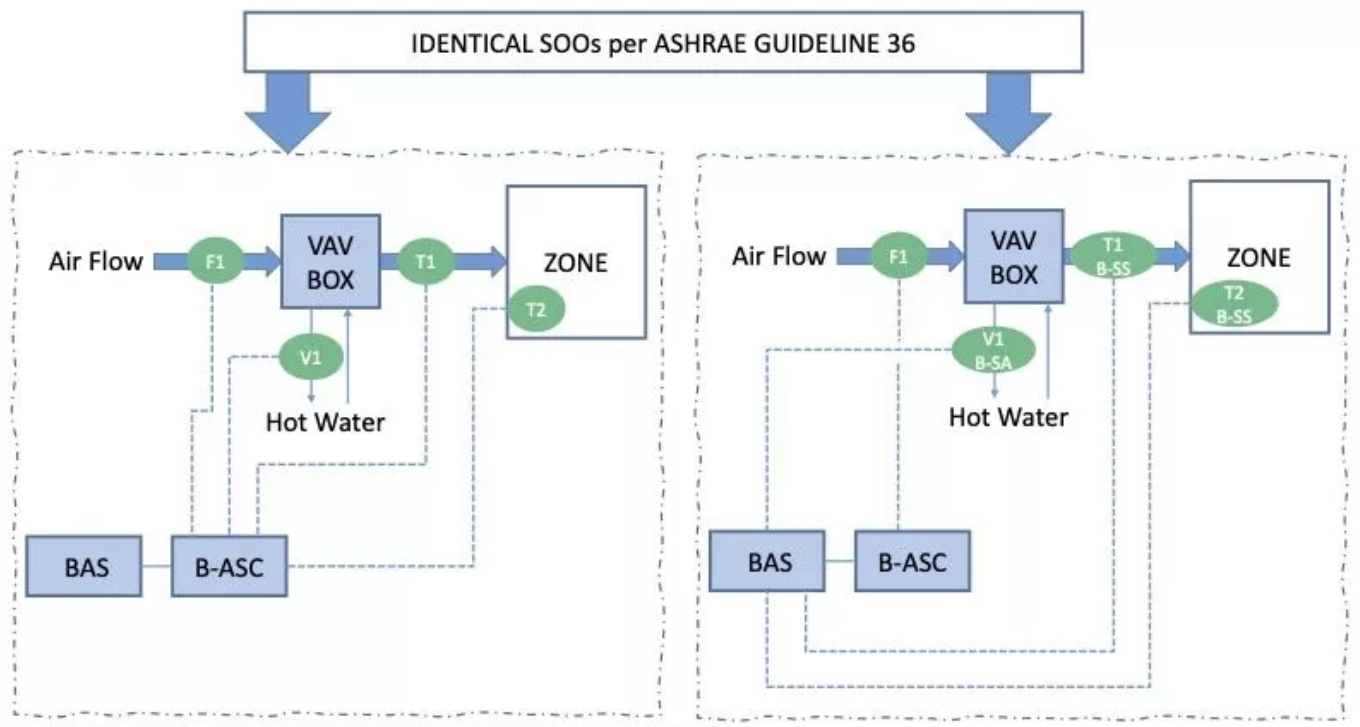
Figure 4: Sample control diagrams.
ASHRAE Guideline 36 is a repository of sequences of operation applicable to HVAC systems that are typically installed in most commercial buildings.
The intent of this guideline is to encourage engineers, contractors, and building owners to use standardized sequences of operation that have been proven over time to be reliable and to operate systems in an energy-efficient manner. These proposed control sequences are sensor and actuator agnostic. In the context of this example, being sensor and actuator agnostic means it doesn’t matter if a building automation system has standard sensors and actuators or BACnet sensors and actuators; the outcome (i.e., the energy consumption of the building systems) will most likely be the same.
Referring back to the first example of broad requirements set by a building’s owner about what constitutes a smart building, and assuming the building HVAC system is programmed to operate based on the sequences of operation defined in ASHRAE Guideline 36, what value does the owner get if the energy efficiency of the building is the same, regardless of the type of sensors used? It may be that an owner finds the marketing aspect of using smart sensors extremely valuable, in addition to the value of having an energy-efficient building. You could reasonably infer the building by itself did not become smarter due by using BTL Listed sensors and actuators. Engineers and design professionals should inform building owners about any potential risks and benefits before recommending BACnet sensors and actuators.
Figure 5 shows a sample building automation system network architecture connected to the cloud. In this scenario, the local controllers, typically the BACnet Application Specific Controllers (B-ASC), are connected to the building automation system network and also to the cloud. What makes these controllers edge controllers is the fact they are located at the edge (periphery) of the BACnet network. These types of controllers have significantly more capabilities (i.e., memory, processing speed, storage capacity, etc.) than typical B-ASC devices; this is because they must be able to execute the standard proportional-integral-derivative loops required to control the associated HVAC equipment and, at the same time, respond to requests (i.e., sending data) from the cloud-based applications.
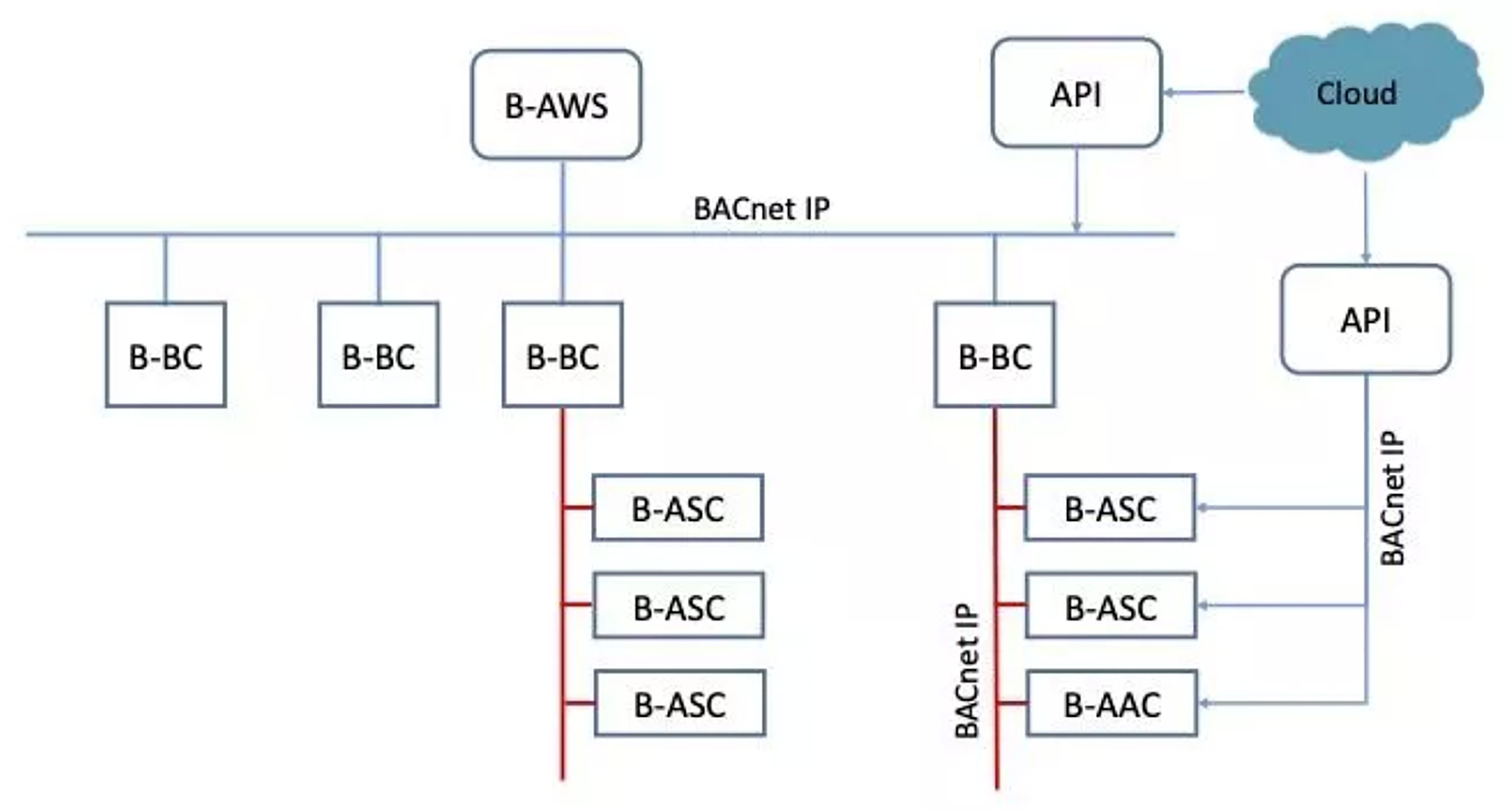
Figure 5: Sample building automation system architecture connected to the cloud.
An application programming interface (API) is typically needed to facilitate the communication between the cloud-based applications and the edge controllers. An API is a collection of software applications that collect and prepare the data before sending it to cloud-based applications. Although building automation systems have the capability to store and trend data and provide alarms, anomaly-detection applications are typically cloud-based. This is because they typically require more computational power to execute various algorithms that cannot be supported by typical BACnet building controllers.
Fault detection and diagnosis is the process of identifying or detecting deviations from normal or expected operation (faults) and resolving (diagnosing) the type of problem or its location.
Figure 6 shows an anomaly in the operation of the VAV box in Figure 4. At a certain time during the day, the VAV box leaving air temperature exceeded an expected maximum value of 85°F. The building automation system could issue an alarm once it detects this condition, but in the case of the more complex scenario shown in Figure 7, the building automation system may not be able to detect the anomaly.
.
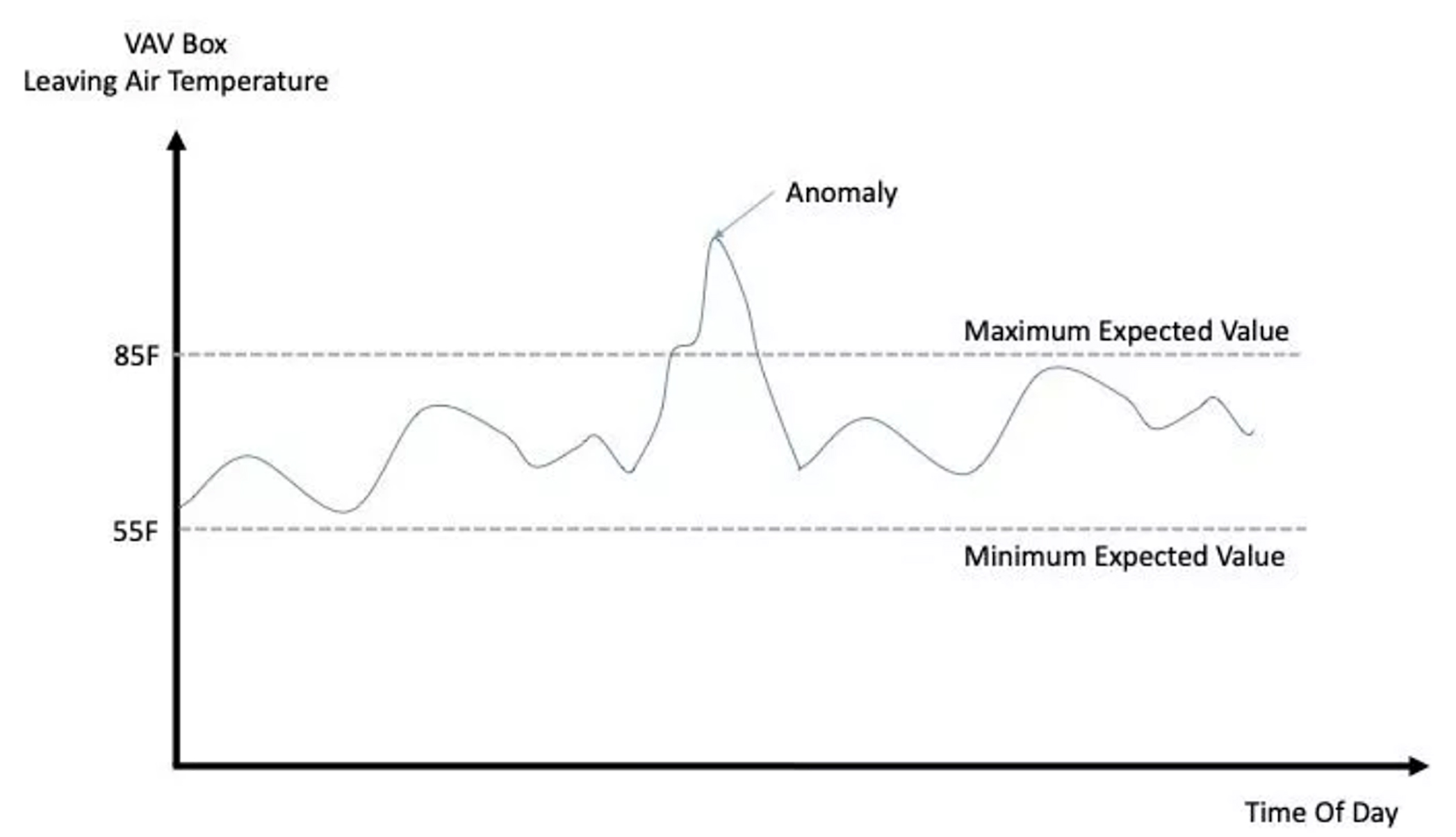
Figure 6: Simple anomaly in building automation system trends.
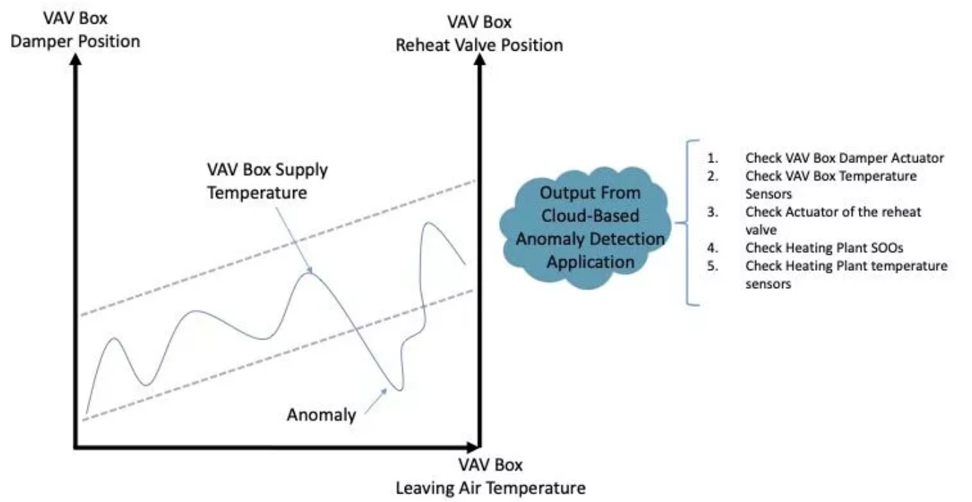
Figure 7: Complex anomaly in the operation of a VAV box.
In this scenario, even though the VAV box reheat control valve is almost fully open, the VAV box leaving air temperature is below an expected range. It may be an indication that either more airflow is going through the box than expected (even though damper is not as open) or the temperature of the water entering the coil is not as warm as expected, which, in turn, caused a reduction in the heating capacity of the VAV box. The output from an anomaly-detection software application may be a series of actions for the user to implement to determine the cause of the anomaly.
Anomaly-detection applications can play a significant role in the operation of an HVAC system. Anomalies that go undetected can result in systems using more energy than expected. For example, an owner may use the output from a predictive energy model as a reference to predict future operating costs. Anomalies (e.g., chiller plant using 20 percent more energy than predicted) may negatively impact an owner’s cash flow. Undetected anomalies can also affect the preventive maintenance efforts of a facilities team by reducing the useful life of equipment. This in turn may also negatively impact an owner’s cash flow associated with the operation of the building.
Referring back to the second example of broad requirements set by a building’s owner about what constitutes a smart building, are analytics, anomaly-detection, and artificial intelligence (AI) applications enough to classify a building as smart or green?
For this example, neither the building automation system nor the other three types of applications can help in identifying what caused the anomaly. Giving a building automation system user a series of actions to execute to find the cause is helpful, but implementing the actions takes time, and when a facilities team is short-staffed, finding the cause of the anomaly and then fixing the issue may not prevent the building from running inefficiently for prolonged periods of time.
Identifying the cause of an anomaly most likely requires the implementation of causal algorithms in addition to the three other types of applications. AI algorithms by themselves are not enough to make a building smart. Causal algorithms are not AI algorithms. AI algorithms take data input at face value. They assume the input is correct (i.e., garbage in, garbage out). AI algorithms cannot determine if a portion of the training data is incorrect or if it includes anomalies. Causal algorithms are used to find the cause behind an anomaly with minimal to no human intervention. Causal algorithms are extremely difficult to program at scale, and the industry is just not there. AI algorithms to control building systems are simply not enough to make a building smart and minimize its impact on the environment (Figure 8). The industry needs to keep pushing for more advanced algorithms.
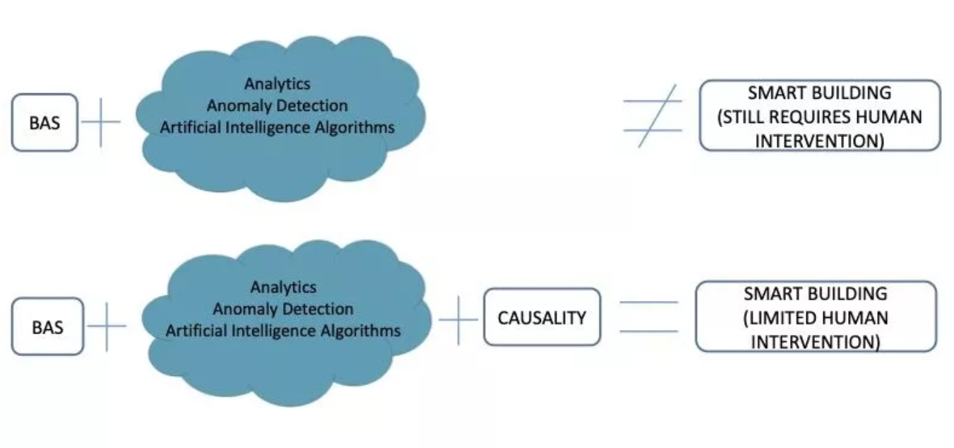
Figure 8: Limitations of standard applications.
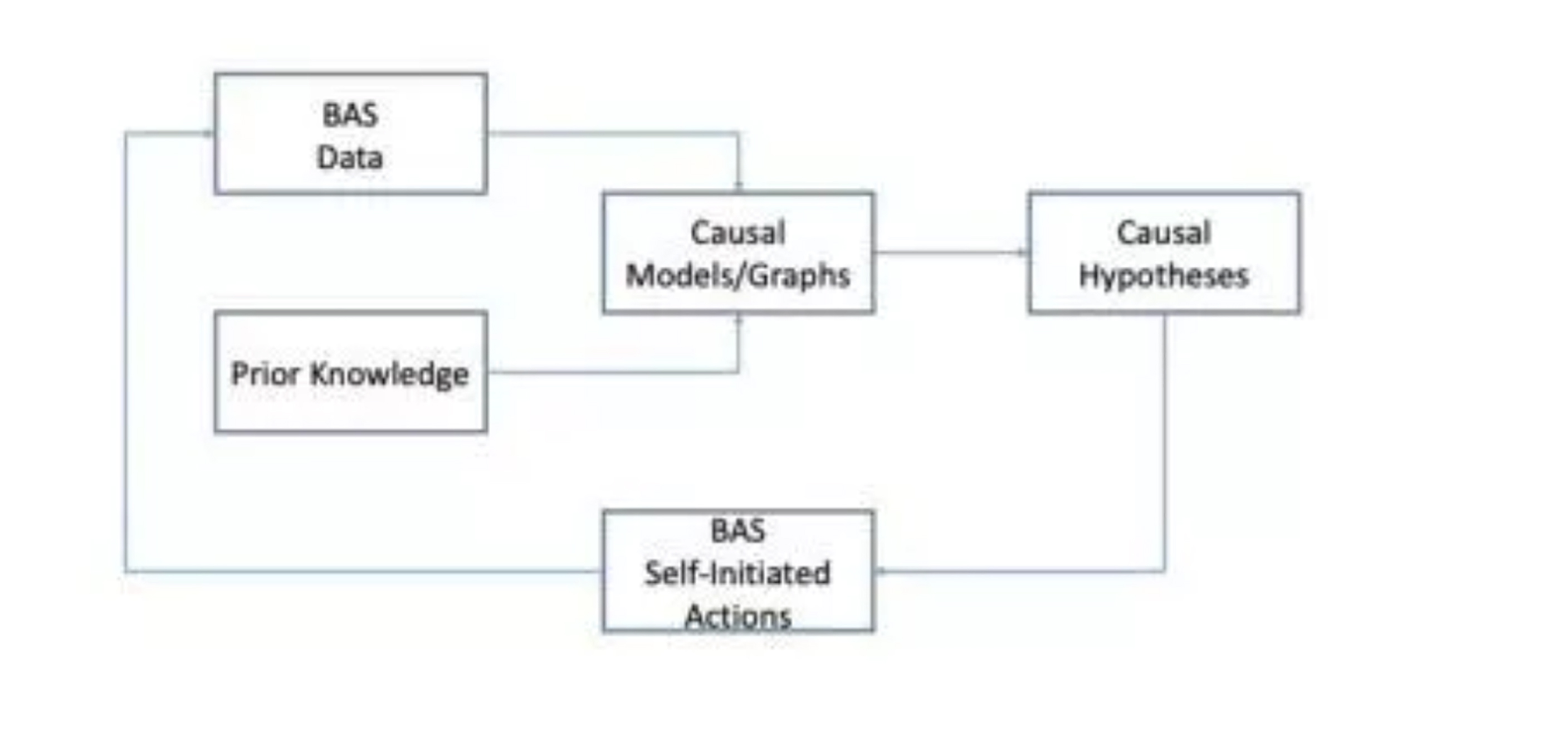
Figure 9: Causal discovery workflow.
A causal model is typically built using a direct acyclic graph (DAG), which is a graph between a set of variables connected by arrows. A path in a directed graph is a nonrepeating sequence of arrows that have endpoints in common. In a DAG a variable cannot have a path toward itself.
Figure 10 shows a sample causal model for the VAV box in Figure 4. Each variable in the DAG represents all historical values available at the building automation system and filtered by a desired timeframe (i.e., the time interval starting with one hour before the anomaly occurred and up to two hours after). The purpose of the graph is to identify what caused the VAV box supply temperature to be outside its expected range. An arrow from one variable to another variable—from F1 to T1—represents that F1 is a direct cause for T1.
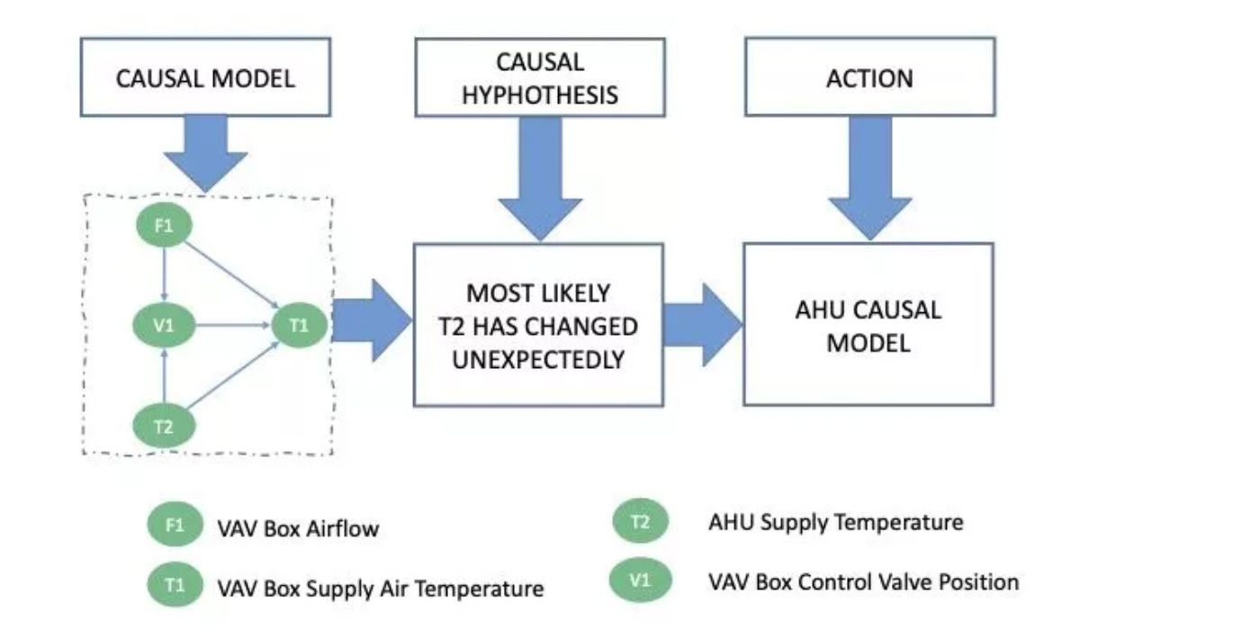
Figure 10: Sample causal model for VAV box.
For example, if the reheat valve doesn’t continue to open, an increase in airflow of the VAV box has a direct effect on the VAV box supply air temperature. The causal model also includes the air-handling unit supply-air temperature (variable T2), which has a direct effect on T1 and an indirect effect on T1 (via variable V1). The outcome from this causal model may be that the air-handling unit supply temperature has changed unexpectedly. The causal algorithm will then create a new causal model of the air-handling unit as whole to identify what caused the air-handling unit supply-air temperature to drop.
Causal models used with high-performing building automation systems (including analytics, anomaly detection, and AI algorithms) have the potential to help facility operators better maintain building systems and operate them in the most energy-efficient way possible while meeting the owner’s requirements.
Do you design building automation systems? Our website offers free tools and utilities for building design and automation consultants. Make your life easier, save time, and save effort by registering for a Consultant account on our Reliable Controls Support Center.

How does building automation ensure hospitals are safe, secure, comfortable environments for everyone?

Learn when and why MS/TP communication is helpful in building automation systems.

From the moment you park your car at a hockey arena, your comfort and safety are enhanced through a building automation system. Here’s how.

Building automation systems can make buildings truly intelligent, reducing their carbon footprint and saving money. Learn how.

Ever wonder how a building automation system ensures safety and accuracy in lab work?

Museums—and their building automation systems—play an important role in preserving the preserved. Learn how.

When you see a doctor or personal trainer, you benefit from their knowledge and experience. In the same way, a building automation system should provide all the tools you need to maintain your buildings in optimal health.
What are you doing to mitigate the transmission of viruses indoors? Learn what measures you can take and how your smart building provides more information and control for IAQ concerns.